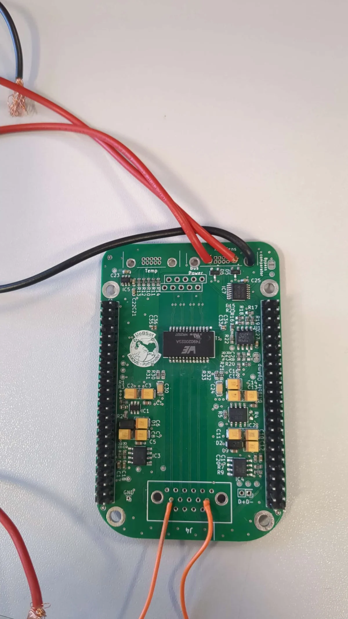
PROVE Pathfinder Main PCB
KiCad 9 CubeSat Space Application
What it is
This is the main interface PCB for PROVE Pathfinder — a satellite mission I’ve been contributing to at Bristol. The board is a hat for a SanCloud BeagleBone Enhanced that sits in the satellite stack and handles all the messy stuff between the spacecraft bus and the payload cameras.
The two cameras are a Basler (12V) and a Tau thermal imager (5V), and the board’s job is to switch power to them safely, moniter current draw, buffer signals during boot, and get ethernet out to the cameras. It also reads a set of thermistor probes for thermal monitoring.
Compute platform — SanCloud BeagleBone Enhanced
The host processor is a SanCloud BeagleBone Enhanced — a Linux SBC based on the TI AM335x (single-core Cortex-A8 at 1 GHz). The BBE was already committed to by the team before this board was designed, so the hat had to work around it rather than influence the choice.
In practice the BBE gives you a comfortable Linux environment, familiar GPIO and device tree tooling, and a functioning Ethernet MAC for talking to the cameras. What it doesn’t give you is much compute headroom, hardware-accelerated ML, or a real-time co-processor — which is part of why the later SoM Interface Board project moved to the DART-MX8M-PLUS.
The BBE’s GPIO behaviour on startup is the key hardware constraint driving a lot of this board’s design: the pins are not high-impedance before the processor boots, so you cannot drive signals into them until the boot sequence has completed. That’s what the comparator gate circuit is for.
Why it needs to exist
The BeagleBone doesn’t have high-impedance GPIO on startup — if you apply voltages to those pins before the processor has finished booting you can cause all sorts of problems. So the board sits between the spacecraft bus and the BBE and gates all the signals behind a comparator circuit that checks the boot state before letting anything through.
The condition is: 5V up, 1.8V up, and SYS_RESETn gone low. Once that’s met the LM393 comparator sends a high to the CD4066B analog switches and the data lines open up. It’s not complicated but it’s the kind of thing that’s easy to miss and tends to bite you during integration.
On top of that, both cameras need individually switched power rails with overcurrent protection, and the satellite stack needs housekeeping telemetry on those rails so ground can see whats happening.
Power switching
Each camera has its own dedicated load switch:
- Basler (12V) — BD1HD500EFJ-CE2, rated to 1.45A overcurrent trip, active-high control. Off by default.
- Tau (5V) — BD2244G-MGTR, same deal. Off by default.
- Thermistor probes (1.8V) — TPS22917, separate switch so the probe voltage can be cut independantly.
Both camera switches are off by default which matters for ground handling — you don’t want cameras powering up the moment the battery is connected.
Current sensing on both rails uses the TMCS1100A4QDRQ1, which gives 400mV/A. The BeagleBone ADC is 1.8V max so with a 500mA worst-case load you’re sitting at about 0.79V with a mid-point of 0.5V
These devices were chosen by previous engineers and I never really liked them due to the incredibly low sensitivity for the ranges of current draw that the cameras are expecting. At worst case, the cameras will draw 500mA and that will result in a maximum range of 0.79V. Any specific current values I feel are too low to the noise floor and will get lost, but there’s a certain amount of institutional desire and faith in these as they’ve used them previously. In an ideal world I’d scrap these hall effect sensors and use something like an INA226 that I’ve used before.
In the other board version where I’m trying to move the group away from the BeagleBone I use eFuse devices (TPS2660) which also provide a current measurement and are much better suited for this purpose than two individual devices.
Ethernet
The Tau camera talks over Gigabit Ethernet, so the board has onboard magnetics (WE-LAN 749020023A) and TVS diode protection on the pairs. Nothing particularly unusual here, mostly just making sure the return path is clean and ESD doesn’t kill the camera during integration.
Form factor & misc
The board is a standard BeagleBone hat with 2×23 2.54mm headers on the bottom (referenced from the bottom side). Connectors out to the spacecraft bus use G125 series — 8-way for bus power, 16-way for data signals, and smaller connectors for each camera and the thermistors.
There’s also a 3-pin UART debug header which was genuinely useful during bring-up.
Test points on every power rail and key signal so you can get a probe on things once the board is in the stack and most connectors are buried.
PCB notes
4-layer stackup. Power traces derated conservatively — in vacuum you can’t rely on convection so the IPC free-air numbers don’t really apply. Thermal pads under the load switches go through filled vias to the ground plane.
Revision history
The board went through a few iterations before we got to something we were happy enough to send off.
v3 / v3.1 (early 2023) — Initial design. Very rough, traces weren’t finished. USB through-hole pads were added for the Tau in this revision. Mostly used for getting the schematic right and working out the connector arrangement.
v0.6 (June 2025) — First manufactured revision. A lot changed getting here from the early version — the ethernet magnetics were swapped out because the original part was obsolete and out of temperature range anyway, TVS diodes were added on the ethernet pairs, zener diodes on the input rails, testpoints added across all the important nets, top-side GND pour with via stitching. LM393 was changed to a VSOP package to save space. Silkscreen was a mess before this too, overlapping pads and mounting holes everywhere.
v0.8 (January 2026) — Second manufactured revision. The main fixes were a SYS_RESETn net that wasn’t connected properly, the off-board connector pitch was changed to 2.54mm (the v0.6 version was a pain to work with), and the differential pair traces to the connector were re-routed from scratch. DRC was re-run and cleared, and the BeagleBone was added as a proper 3D footprint so the 3D view is actually useful.
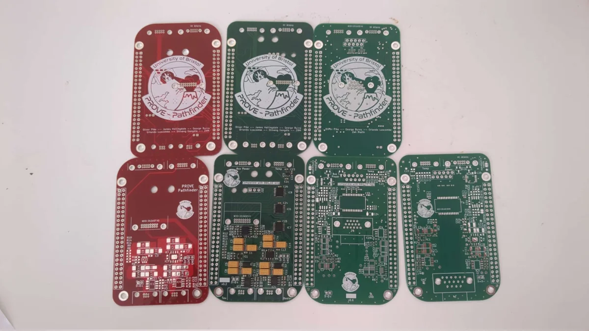
The image above shows the three manufactured revisions side by side, illustrating how the layout and silkscreen tightened up across iterations, as versions were tested and the team gave feedback on what they wanted to change.
Yes, some of the things that they wanted to change could have been known from the start if I’d known precisely what to ask, but such is the way with projects that span across multiple areas of expertise! Some of the changes were smaller than other, but often the changes were large and required a whole do over of the layout, just to accommodate a mechanical design change. But if the board won’t fit inside an enclosure given the current shape and size or where the connectors are, then it doesn’t do its job properly!
Final testing revision
The photo below is v0.8 — the version currently being used for hardware testing and integration with the satellite stack.