
Raspberry Pi CM5 Microscope Carrier PCB
KiCad · Raspberry Pi CM5 · High-Speed Digital · Power Electronics
What it is
This is the carrier board that the microscope camera software stack runs on. The idea was to have something small enough to sit on top of a trinocular microscope head, with everything the compute module needs already on the board no external hubs, no USB dongles, no adapter cables hanging off it.
The CM5 handles all the compute. The carrier board’s job is to connect it to the world: camera, display, storage, power, and controls.
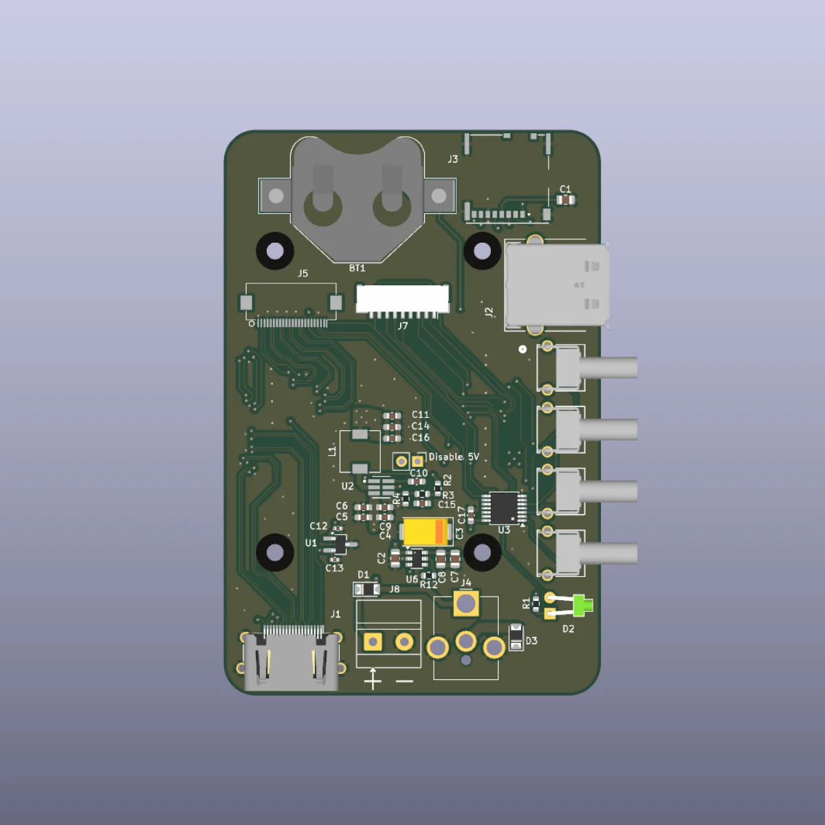
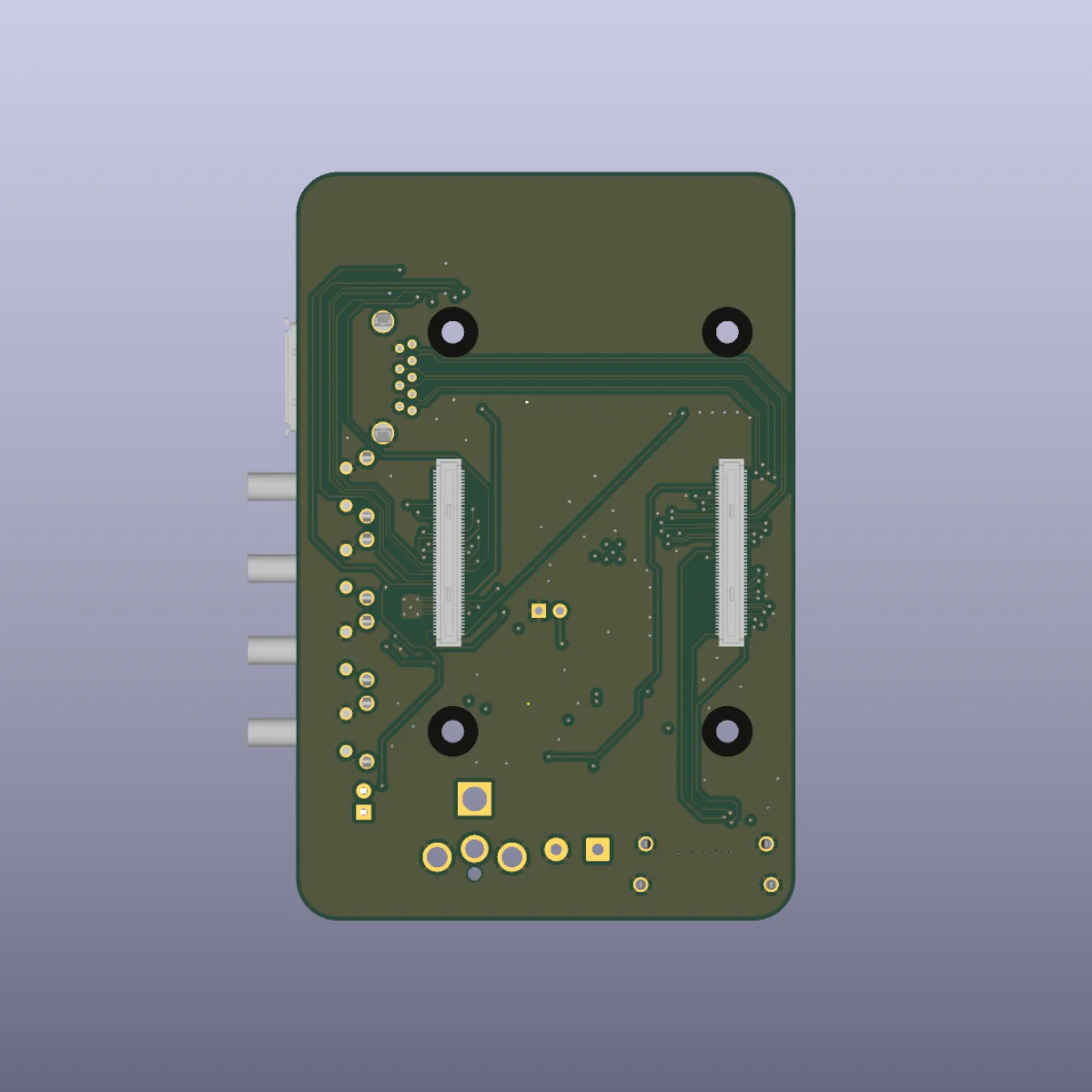
Compute platform — Raspberry Pi CM5
The board hosts a Raspberry Pi Compute Module 5 via the standard high-density board-to-board connector. The CM5 was chosen over a full Pi 5 SBC for two reasons: the carrier can break out exactly the connectors this application needs and nothing else, and the form factor is considerably more compact than any full SBC arrangement would allow.
The BCM2712’s native MIPI CSI-2 lanes are the key feature for this application. Camera data goes directly into the SoC’s on-chip ISP without a bridge chip which means the full-resolution images from the HQ camera are processed in hardware rather than eating CPU cycles. Running libcamera (via picamera2) on a quad-core Cortex-A76 processor also means image processing, autofocus, and all the software features described in the software portfolio page run comfortably without thermal throttling.
Camera — CSI connector
The board breaks out a CSI-2 connector for the Raspberry Pi HQ Camera. The HQ camera uses an IMX477 sensor and mounts to the microscope’s trinocular port via a C-mount adapter, making it a proper optical interface rather than a camera bolted to a stand.
The CSI traces are routed as matched-length differential pairs with controlled impedance. The BCM2712 has a two-lane CSI interface rather than the four-lane standard, which caps the streaming bandwidth this is a hardware limitation of the Pi platform, not a board design choice. The PCB includes breakout test points on the CSI lanes to make it easier to explore higher-bandwidth configurations if the driver situation improves.
Display — Waveshare e-ink connector
A connector for a Waveshare 2.15” four-colour e-ink display. The e-ink choice was deliberate: microscope work is often done on a bench with other equipment, and a display that holds its last image without backlight or refresh makes status information (WiFi network, storage state, current mode) readable at a glance without being distracting. It also draws essentially no power when static, which matters for a board that needs to run continuously.
The display shows system status information like WiFi SSID, USB storage state, camera readiness which is updated by the software stack on state changes.
Storage — USB and SD card
The board provides both USB storage and a microSD card slot. USB storage is the primary target for captures: plug in a drive, images are automatically mirrored to it. The SD card is a nice to have incase I want more storage, or to use as a removable medium.
Having both on the carrier rather than relying on a USB hub or external adapter keeps the board self-contained and means there’s no single-point-of-failure USB hub between the CM5 and storage.
Video output — HDMI
A full-size HDMI connector is broken out from the CM5. Primarily useful during setup and debugging connecting to a monitor to configure the system before it’s on the network but also gives the option to run the microscope directly from an HDMI display without needing a network connection at all.
Controls — four push buttons
Four tactile push buttons on the board:
- WPS : triggers a WPS join on the CM5’s wireless interface so the device can be added to a network by button press, without touching a configuration file or plugging in a keyboard
- Capture : triggers a still image capture from the HQ camera
- User button 1 / User button 2 : assignable in software; currently used for resolution switching and a soft reboot
All four inputs have hardware Schmitt triggers on the switch lines, so the software layer needs no debouncing. GPIO pin assignments for all buttons are configurable from the web interface and persisted to disk, which made early bring-up easier when testing on a bare CM5 before the carrier existed.
RTC — coin cell backup
The CM5 has a real-time clock that loses its time on power loss unless it has a backup supply. The board includes a coin cell holder (CR2032) wired to the CM5’s RTC backup input. This means the board retains the correct time across power cycles and doesn’t need an NTP sync before the clock is usable which si important for correct file timestamps on captures.
Power — 12 V input with ring light supply
The board is powered from a 12 V DC input. An on-board switching regulator steps this down to the rails the CM5 needs (5 V for the module, 3.3 V for peripherals). Running from 12 V rather than 5 V means a standard barrel-jack wall supply or bench supply can power the whole system, and the cable can be reasonably thin for the current involved.
The 12 V input is also routed to an output rail that supplies the ring light under the microscope. Rather than running the ring light from a separate supply or a USB power bank sitting on the bench, the carrier provides the ring light current directly. A single cable from the wall to the PCB powers both the compute side and the illumination. This is just for neatness, and there’s a dimmable knob on the ringlight. Maybe in a future revision I’ll add a PWM dimming circuit to the power to the ringlight so I can changfe the brightness from software.
Skills demonstrated
- High-speed digital routing : MIPI CSI-2 differential pairs with matched-length trace constraints and impedance control
- Multi-rail power supply : 12 V input, switching regulation to 5 V and 3.3 V, ring light MOSFET drive, RTC coin cell backup
- Peripheral integration : CM5 board-to-board connector, SPI e-ink display, USB hub logic, SD card interface, HDMI routing
- Hardware/software co-design : board designed alongside the software stack, with GPIO assignments, Schmitt trigger debouncing, and CSI test points informed by bring-up requirements
- Full PCB layout in KiCad : placement, routing, DRC, and fabrication outputs